

UPVC fishing buoy extruder head
欄目:Industry News 發布時間:2021-06-03 15:19
UPVC fishing buoys are a kind of fishing gear used by coastal fishermen for marine operations. They are required to have high compressive strength, seawater corrosion resistance, large buoyancy and high impact strength. The production of fis...
UPVC fishing buoys are a kind of fishing gear used by coastal fishermen for marine operations. They are required to have high compressive strength, seawater corrosion resistance, large buoyancy and high impact strength. The production of fishing buoys adopts the process route of extrusion blow molding with PVC resin as the material. The basic formula and process flow are as follows (unit kg):
PVC resin (SG-6): 100.00
Plasticizer: 8.00~12.00
Heat stabilizer: 4.00-5.00
Metal soap salt: 1.50~2.00
Paraffin: 0.50-1.00
Filling agent: 1O. Oo~2O. 00
High-speed mixing of the above materials _+ low-speed cold agitation _+ extruder (SJ-65) melt plasticizing machine head extrusion tube blank _+ shear blank _ + mold inflation _ + pressure-holding cooling stereotype - ÷ exhaust Mode air cooling _+ trimming _ + sealing pinhole _ + water pressure test _ + inspection of finished products. It is not difficult to see from the process flow whether the molten material flows through the extruder to successfully extrude the tube blank, which ultimately affects the output and quality of the fishing buoy. Therefore, the design of the head must be reasonable and effective.
1 Extrusion head structure and its working process
1.1 Extrusion head structure
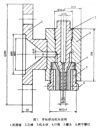
The structure of the extruder head is shown in Figure 1.
1.2 Working process
After the molten material is extruded from the splitter plate (porous plate), it is compressed into the circular hole of the head body through the neck seat to reach the mandrel. Under the barrier of the mandrel, the melt is divided into two strands that flow around the mandrel and rejoin on the other side of the mandrel. After the molten material is merged, it is rotated 90~ along the annular gap formed between the mandrel and the head body and the die to further compress the flow, and finally extruded into a tube blank.
2 Extrusion head design requirements and key points discussion
2.1 Extrusion head design requirements
(1) The tube blank of the extruder head should have a uniform flow rate at any position on the circumference.
(2) The flow path of the machine head is smooth and streamlined, and no obvious dead angle is generated, and the flow path section should be continuously reduced to form a certain compression ratio.
(3) The temperature of the head can be accurately controlled and the temperature distribution is uniform.
(4) The structure of the machine head is as compact as possible, the connection with the barrel is tight, the parts are few, the assembly and disassembly is convenient to maintain, and the manufacturing cost is low.
2.2 Extrusion head design points
(1) The neck seat (piece 1) is flanged to the extruder barrel, and the inner cavity port is used for placing a stainless steel perforated plate to change the molten material from a rotary motion to a linear motion, and also to prevent impurities and unplasticized. The material passes. The central portion of the inner cavity is designed to have a compression angle of 30. ~45. The bell mouth is used to generate the necessary molding pressure to increase the flow rate of the fabric flow. The neck seat and the head body (item 3) are connected by multi-point welding.
(2) The mandrel (part 2) is one of the important components of the formed tube blank, the upper end of which is screwed to the head body (piece 3), and the top end is the wrench working position, so designed to clean the head and prevent the mandrel It is more advantageous. In the axial direction of the mandrel, a central hole having different apertures and communicating is drilled. On the one hand, the thermometer can be inserted for short-term detection of the temperature of the head; on the other hand, the phenomenon of "collapse" after the blank leaves the die can be prevented. In addition, the core hole drilling has a certain effect on preventing the core rod from overheating. The determination of the length L of the straight portion of the mandrel is important. The large value of L is favorable for the flow direction and the cross-sectional area of ​​the melt to be well rectified in this area, and it is also advantageous to eliminate the weld line, but the head back pressure is increased. Generally take L / S = 15 ~ 20, S is the gap between the flat part of the mandrel and the die (item 4) (referred to as the die gap).
(3) As can be seen from Figure 1, to ensure the annular gap of the nozzle outlet
Uniform, set the die (key 4, or adjustment ring) and adjustment screw (key 6). The die is fastened to the lower part of the nose by a hollow screw head (44 5, M52mrnx3mm). A proper gap is reserved between the cylindrical surface of the inner hole of the screw head and the outer surface of the die to adjust the die gap. The number of adjustment screws that are placed on the hollow screw head is generally three. If too much, the adjustment is complicated. Determining the die inner diameter D is usually calculated based on the blow ratio a. The inflation ratio a is the ratio of the maximum outer diameter D of the product to the inner diameter Dk of the die. It is usually taken in practical applications.
The outer diameter of the flat part of the mandrel, S is the gap width of the die, generally according to the relationship: the die gap width S = product wall thickness tx inflation ratio a × correction coefficient b is calculated, after finishing: the correction factor b is usually Determined by experiment. If it is known that the buoyancy 40gUPVC fishing buoy has a central outer diameter D=38mm, a wall thickness t=2mm, an inflation l:ka=2, and a blow molding of UPVC plastic takes b:1.1,
(4) The head body (item 4) is designed to grow into a cylinder of 104 mm and a cross-sectional diameter of ~b70 mm. The body structure is advantageous for the installation of the electric heater, and is also advantageous for uniform heating of the melt flowing through the machine head and convenient machining. In order to accurately control the temperature of the head, a thermocouple insertion hole (not shown in Figure 1) should be machined on the body.
3 Problems with the extruder head
(1) The melt flows from the neck to the mandrel and is immediately divided into two and flows around the mandrel, and then converges on the other side of the mandrel, point A, and then turns at a corner of 90. Flows in the direction of the die. It can be seen that the flow velocity at A is the slowest, and it is prone to stagnation decomposition, which in turn causes sticking to the wall, and finally causes longitudinal decomposition of the extruded tube blank, which seriously damages the appearance quality of the buoy and affects its mechanical properties. The solution is to make the convergence point A move down properly, so as to avoid the phenomenon of decomposed decomposition. If no improvement is made, at least the cleaning head should be shut down 2 to 3 times in each shift, and the temperature of the head should be controlled, and the thermal stability and melt flow of the material can be improved in the formulation.
(2) The mandrel rod is fixed by threaded connection in the machine head body, which is convenient for storing the cleaning head. However, as the number of cleaning times increases, the loose teeth will eventually be produced, and the mandrel must be replaced or improved. .
PVC resin (SG-6): 100.00
Plasticizer: 8.00~12.00
Heat stabilizer: 4.00-5.00
Metal soap salt: 1.50~2.00
Paraffin: 0.50-1.00
Filling agent: 1O. Oo~2O. 00
High-speed mixing of the above materials _+ low-speed cold agitation _+ extruder (SJ-65) melt plasticizing machine head extrusion tube blank _+ shear blank _ + mold inflation _ + pressure-holding cooling stereotype - ÷ exhaust Mode air cooling _+ trimming _ + sealing pinhole _ + water pressure test _ + inspection of finished products. It is not difficult to see from the process flow whether the molten material flows through the extruder to successfully extrude the tube blank, which ultimately affects the output and quality of the fishing buoy. Therefore, the design of the head must be reasonable and effective.
1 Extrusion head structure and its working process
1.1 Extrusion head structure
The structure of the extruder head is shown in Figure 1.
1.2 Working process
After the molten material is extruded from the splitter plate (porous plate), it is compressed into the circular hole of the head body through the neck seat to reach the mandrel. Under the barrier of the mandrel, the melt is divided into two strands that flow around the mandrel and rejoin on the other side of the mandrel. After the molten material is merged, it is rotated 90~ along the annular gap formed between the mandrel and the head body and the die to further compress the flow, and finally extruded into a tube blank.
2 Extrusion head design requirements and key points discussion
2.1 Extrusion head design requirements
(1) The tube blank of the extruder head should have a uniform flow rate at any position on the circumference.
(2) The flow path of the machine head is smooth and streamlined, and no obvious dead angle is generated, and the flow path section should be continuously reduced to form a certain compression ratio.
(3) The temperature of the head can be accurately controlled and the temperature distribution is uniform.
(4) The structure of the machine head is as compact as possible, the connection with the barrel is tight, the parts are few, the assembly and disassembly is convenient to maintain, and the manufacturing cost is low.
2.2 Extrusion head design points
(1) The neck seat (piece 1) is flanged to the extruder barrel, and the inner cavity port is used for placing a stainless steel perforated plate to change the molten material from a rotary motion to a linear motion, and also to prevent impurities and unplasticized. The material passes. The central portion of the inner cavity is designed to have a compression angle of 30. ~45. The bell mouth is used to generate the necessary molding pressure to increase the flow rate of the fabric flow. The neck seat and the head body (item 3) are connected by multi-point welding.
(2) The mandrel (part 2) is one of the important components of the formed tube blank, the upper end of which is screwed to the head body (piece 3), and the top end is the wrench working position, so designed to clean the head and prevent the mandrel It is more advantageous. In the axial direction of the mandrel, a central hole having different apertures and communicating is drilled. On the one hand, the thermometer can be inserted for short-term detection of the temperature of the head; on the other hand, the phenomenon of "collapse" after the blank leaves the die can be prevented. In addition, the core hole drilling has a certain effect on preventing the core rod from overheating. The determination of the length L of the straight portion of the mandrel is important. The large value of L is favorable for the flow direction and the cross-sectional area of ​​the melt to be well rectified in this area, and it is also advantageous to eliminate the weld line, but the head back pressure is increased. Generally take L / S = 15 ~ 20, S is the gap between the flat part of the mandrel and the die (item 4) (referred to as the die gap).
(3) As can be seen from Figure 1, to ensure the annular gap of the nozzle outlet
Uniform, set the die (key 4, or adjustment ring) and adjustment screw (key 6). The die is fastened to the lower part of the nose by a hollow screw head (44 5, M52mrnx3mm). A proper gap is reserved between the cylindrical surface of the inner hole of the screw head and the outer surface of the die to adjust the die gap. The number of adjustment screws that are placed on the hollow screw head is generally three. If too much, the adjustment is complicated. Determining the die inner diameter D is usually calculated based on the blow ratio a. The inflation ratio a is the ratio of the maximum outer diameter D of the product to the inner diameter Dk of the die. It is usually taken in practical applications.
The outer diameter of the flat part of the mandrel, S is the gap width of the die, generally according to the relationship: the die gap width S = product wall thickness tx inflation ratio a × correction coefficient b is calculated, after finishing: the correction factor b is usually Determined by experiment. If it is known that the buoyancy 40gUPVC fishing buoy has a central outer diameter D=38mm, a wall thickness t=2mm, an inflation l:ka=2, and a blow molding of UPVC plastic takes b:1.1,
(4) The head body (item 4) is designed to grow into a cylinder of 104 mm and a cross-sectional diameter of ~b70 mm. The body structure is advantageous for the installation of the electric heater, and is also advantageous for uniform heating of the melt flowing through the machine head and convenient machining. In order to accurately control the temperature of the head, a thermocouple insertion hole (not shown in Figure 1) should be machined on the body.
3 Problems with the extruder head
(1) The melt flows from the neck to the mandrel and is immediately divided into two and flows around the mandrel, and then converges on the other side of the mandrel, point A, and then turns at a corner of 90. Flows in the direction of the die. It can be seen that the flow velocity at A is the slowest, and it is prone to stagnation decomposition, which in turn causes sticking to the wall, and finally causes longitudinal decomposition of the extruded tube blank, which seriously damages the appearance quality of the buoy and affects its mechanical properties. The solution is to make the convergence point A move down properly, so as to avoid the phenomenon of decomposed decomposition. If no improvement is made, at least the cleaning head should be shut down 2 to 3 times in each shift, and the temperature of the head should be controlled, and the thermal stability and melt flow of the material can be improved in the formulation.
(2) The mandrel rod is fixed by threaded connection in the machine head body, which is convenient for storing the cleaning head. However, as the number of cleaning times increases, the loose teeth will eventually be produced, and the mandrel must be replaced or improved. .
 Scan our WeChat official account
|